The relationship between acceleration, velocity and displacement under stationary vibration conditions is often misunderstood. Since the implications of these requirements on vibration test equipment requirements should be understood to insure that the correct size and type of equipment is specified, the following may prove useful.
It is important to understand that with sinusoidal vibration, the relationship between acceleration, velocity and displacement is fixed and frequency dependent. It is not possible to vary any one of these three parameters without affecting another, and for this reason, one must consider all of them simultaneously when specifying or observing sine vibration.
The three parameters of acceleration, velocity and displacement are all linear scalar quantities and in that respect, at any given frequency, each has a constant, proportional relationship with the other. In other words, if the frequency is held constant, increasing or decreasing the amplitude of any one of the three parameters results in a corresponding proportional increase or decrease in both of the other two parameters. However, the constant of proportionality between the three parameters is frequency dependent and therefore not the same at different frequencies.
In general, sinusoidal vibration testing uses the following conventions for measurement of vibration levels.
Acceleration is normally specified and measured in its peak sinusoidal value and is normally expressed in standardized and normalized dimensionless units of g's peak. In fact, a g is numerically equal to the acceleration of gravity under standard conditions, however, most vibration engineering calculations utilize the dimensionless unit of g's and convert to normal dimensioned units only when required.
Velocity is specified in peak amplitude as well. Although not often used in vibration testing applications, velocity is of primary concern to those interested in machinery condition monitoring. The normal units of velocity are inches per second in the English system or meters or millimeters per second in the metric system of units.
Displacement is usually expressed in normal linear dimensions, however, it is measured over the total vibration excursion or peak to peak amplitude. The normal units of displacement are inches for English or millimeters for the metric system of units.
As mentioned previously, these quantities are not independent and are related to each other by the frequency of the vibration. Knowing any one of these three parameter levels, along with the frequency of operation, is enough to completely predict the other two levels. The sinusoidal equations of motion stated in normal vibration testing units are as follows.
where:
g= acceleration, g's peak
D= displacement, inches, peak to peak
V= velocity, inches per second, peak
f = frequency, Hz
Inspection of the above equations shows a couple of important relationships that, if understood, will make using and specifying vibration tests easier.
The first is the squared frequency relationship between displacement and acceleration. Analysis shows that for normal sine testing, the displacements above 80 or 100 Hz are generally small. Conversely, if acceleration is held constant and the frequency is lowered, displacement increases rapidly with the frequency change. This can come as a surprise to those new to vibration and has resulted in more than one damaged system and test article.
The second is that velocity has a proportionally increasing (or decreasing) relationship with either displacement or acceleration. In other words, the velocity will increase (or decrease) in direct proportion to the frequency if either of the other two parameters are held constant. Velocity is of interest when damping components or back EMF issues are important to the testing.
A complete matrix of the sinusoidal equations of motion is presented in the Engineering Data Reference section of this catalog.
By far the most common type of sine testing involves a logarithmic frequency sweep holding a specified acceleration constant at the base of a test article or its mounting bosses on the test fixture. A control feedback accelerometer is mounted in the desired position on the fixture and the level is maintained as the frequency of vibration is swept. This method insures excitation at all frequencies between the sweep end frequencies. This type of testing usually will cycle the vibration up and down repetitively between frequency limits for a specified time or number of sweep cycles to ensure that adequate reliability levels are attained.
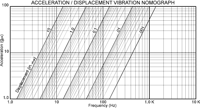
If the testing requires low frequencies, the limitation of the shaker/system available displacement may require lowering the test acceleration. From the nomograph above, displacement limitations are often required and specified. A typical sine test specification might be as follows.
Typical
sine sweep test specification:
Sinusoidal vibration with bidirectional 1.0 octave/minute logarithmic swept
frequency between 5 and 1000 Hz, maintaining a level of 10 g's pk except
as limited by .75 inches pk-pk, 20 sweep cycles total.
It can be seen from the graph above and the previous engineering equations that the vibration level should be 10 g above 16.2 Hz and .75 inches pk-pk below this "Crossover frequency". Most servo sweep vibration controllers are designed to facilitate this type of testing.
Also common are single frequency dwell tests that specify a single critical frequency and acceleration or displacement level and a dwell time. Less common are manual resonance survey, automatic resonance dwell, sine-on-random and many other sine test specifications requiring sophisticated control systems often involving multiple feedback accelerometers.
Once the vibration level requirements are defined for testing purposes, a vibration system can be specified. Since electrodynamic shakers are primarily force generators, the available systems use force output as their primary rating. The maximum required force for any given specification generally will correspond to the portion of the specification having the highest acceleration. It is common to size a shaker system for a given test by assuming that the load is non-resonant and calculating the requirement for a dead mass load of equivalent weight.
All of the elements connected to the armature must be considered part of the dynamic load. This includes the shaker armature itself, any test article mounting fixture as well as the test article.
Refer to the equations shown in the system ratings section of this catalog for the applicable calculations.