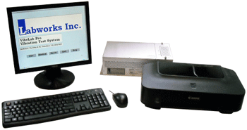
Labworks VibeLab Controllers:
Unmatched in performance/cost value

— General Specifications and Features —

 Complete Controller System Includes:

  - Computer
  - VibeLab and Windows™ software installed and tested, ready to run
  - Monitor
  - Keyboard
  - Mouse
  - Printer
  - VibeLab Shaker interface PC board w/accel. bias supply(s) installed and tested
  - Accelerometer package: (1) -100 mV/g accelerometer, cable, stud, and mounting base


General Description
 

The Gen II VibeLab Vibration Controller is an industrial computer-based vibration test controller. Running under the Windows™ operating system, the controller is designed to generate and run user-defined vibration tests. The electrical output of the VibeLab controller is a real-time voltage signal suitable for use in driving most commercially available wide band vibration test systems. VibeLab utilizes vibration acceleration feedback from one or two accelerometers mounted on the shaker, fixture, and/or test article.

Taking full advantage of the Windows™ environment, VibeLab provides a comfortable and straight forward user interface that allows creation and running of vibration tests with minimal time spent learning to use the controller. All critical settings are software interlocked and cross checked to insure that only valid tests are generated. The virtual instrument approach to the controller user interface puts all of the user required settings and parameters in view, with minimal hidden menu activity required in defining or running a vibration test.

During test program generation, VibeLab considers the user's vibration system and test load characteristics in its calculations to insure that all testing specified is within the capabilities of the particular system. While running the test, VibeLab can be configured to monitor the vibration system operating level and even abort its operation if exceeded. Most common vibration systems are included in the VibeLab system library or the user can easily define and store custom system parameters.

Full output metering is provided during both program generation and vibration testing. Metric or English units are displayed based on the user preference and automatic conversion from one unit system to the other simplifies acceleration and displacement calculations. Acceleration, velocity, and displacement are all displayed simultaneously. The program screen meters display the acceleration, velocity, and displacement of the programmed reference levels during the programming phase. Any parameter exceeding the capabilities of the vibration test system are flagged on the screen and the effects of changes to the programmed levels are instantly shown on the meters. Full metering is also displayed in the run test screen, giving the current level of the control channel acceleration, velocity, and displacement as well as the individual channel acceleration, velocity, and displacement for sine vibration.

Sinusoidal vibration control can be configured to either of the input channels, the average of the two channels, or extremal (highest acceleration of the two channels). The Sine controller can be programmed for frequency sweeping logarithmically, linearly, step to programmed break points, step at even 1 Hz increments, or resonance search and dwell. In addition, its transducer calibration mode can record calibration sensitivity automatically at each user-defined calibration frequency and level.

Random vibration control can be configured to either of the input channels, the average of the two channels, or the extremal (highest acceleration of the two channels). The controller run time can be configured for continuous, external, timed, or cycling testing. Continuous testing is controlled using manual start and stop commands. External start and stop is easily performed in response to a simple switch or relay closure. A four function, re-setable timer is programmable to perform cycled or timed shut down testing as required.

Shock vibration control can also be configured to either of the input channels, the average of the two channels, or extremal. The controller can be configured for manual or automatic pulse triggering during both the equalization phase as well as the full test pulse phase. Automatic shock pulse triggering can be terminated after a set number of pulses or a total elapsed time has been reached. External control can also be used to start and stop automatic shock pulse generation. Shock analysis includes frequency, time and shock spectrum domains.

VibeLab incorporates a sophisticated three-tier password system that allows for individual programming and test running functions access based on password codes. A limited access VibeLab internal calibration control panel along with calibration log are provided to facilitate periodic VibeLab calibration.

Individual vibration test programs can be stored with all display, system, channel, control, etc. information included for instant recall of a particular test setup. In addition to VibeLab's vibration system library and program memory, individual test results can be stored along with any program or setup changes in effect. These stored tests can be easily recalled for continued testing, re-analysis, or delayed report generation. In addition to stored programs and tests, VibeLab retains a preferences program file that is automatically loaded whenever the system is turned on. These preferences are easily changed and saved by the user.

An automatic test log is recorded as the test is run including time stamping all pertinent changes to the test under progress. This Log can be printed directly to the printer or copied to the PC clipboard for transfer to another Windows™ program for inclusion. Up to 10 complete sets of data can be included with saved test data. One complete data set is automatically saved as the "Last Test" whenever the system is stopped. All saved data can be recalled and re-analyzed at any time to allow for custom report generation or delayed analysis.

VibeLab's primary report output is graphical. Either a single large or two smaller graphs can be prepared and printed directly, or copied, to the PC clipboard for inclusion on other Windows™-based applications. Each graph carries its own notation field that prints automatically in the direct print mode. The test log header includes the name of the parent test program for reference. Any two data sets can be displayed on each graph and cross hairs are provided for specific level or frequency identification if required. The data files saved are spreadsheet compatible for custom report generation.


Features Table
 
Controller
 
Feature
VL-144x
VL-145x
VL-145s
VL-145r
Details
           
General Features          
  Dual Mode Acceleration Input Channels
2
1
1
1
 
  Windows-based Virtual Instrument VibeLab Software
Y
Y
Y
Y
 
  Full Featured Online Help, Indexed and Searchable
Y
Y
Y
Y
  Pointer and Context Sensitive Help
Y
Y
Y
Y
  Three-Level, Individual Function Password Access
Y
     
  Dynamic Graph Control w/Auto Scale and Zoom
Y
Y
Y
Y
  Dynamic Breakpoint Entry and Edit w/Auto Calc.
Y
Y
Y
Y
 
  Input Channel Sensitibity w/Program Cross-Check
Y
Y
Y
Y
 
  Vibration System Specification w/Pgm Cross-Check
Y
Y
Y
Y
 
  Vibration System Library
Y
Y
Y
Y
 
  Vibration System Run Level Monitor w/Abort
Y
Y
Y
Y
 
  Program Save and Recall w/Memo and Header
Y
Y
Y
Y
 
  Preferences Program Auto Load
Y
Y
Y
Y
 
  Program Graph Screen w/Vibration Level Meters
Y
Y
Y
Y
 
  Demonstration/Learn mode w/Auto Loop
Y
Y
Y
Y
 
  Direct Graph Print Function or Graph to Clipboard
Y
Y
Y
Y
 
  Test Log Direct Print or Log to Clipboard
Y
Y
Y
Y
 
  Complete Test Data Save/Recall/Resume
Y
Y
Y
Y
 
  Full Featured Timer, w/Shutdown, Hold, Reset, etc.
Y
Y
Y
Y
 
  Exteranl Run/Stop Switch/TTL Interface
Y
Y
Y
Y
 
  Keyboard Emergency Stop/External E. Stop Interface
Y
Y
Y
Y
 
  External Alarm Output
Y
Y
Y
Y
 
  Run Time System Operating Level Display w/Abort
Y
Y
Y
Y
 
  Run Time Real Time Data Display Graphs
Y
Y
Y
Y
  English or Metric Units w/Auto Convert Calc.
Y
Y
Y
Y
 
  Ten Complete Data Set Memory (each test)
Y
Y
Y
Y
  Periodic System Calibration Panel w/Memo
Y
Y
Y
Y
  Date and 24-Hour Clock and Time Stamp
Y
Y
Y
Y
 
VL-144x
VL-145x
VL-145s
VL-145r
Details
Sinusoidal Vibration
Y
Y
Y
 
 
  Single Channel Control
Y
Y
Y
 
 
  Average Control
Y


  Extremel Control
Y


  Resonance Search and Dwell Mode
Y


  Transducer Calibration Mode
Y


  Transmissibility Ch1/Ch2
Y


  Transmissibility Ch1/Drive  
Y


  Servo Speed Adjust
Y
Y
Y
 
 
  Open Loop Trip Level Adjust
Y
Y
Y
 
 
  Cursor Key Manual Control Operation
Y
Y
Y
 
 
  Log, Linear, Dkpt. Step, and 1 Hz Step Sweep Modes
Y
Y
Y
 
 
  Sweep Cycle/Rate Auto Calcualtion Function
Y
Y
Y


  Auto Frequency Sweep w/Manual Controls

Y
Y
Y
 
 
  Manual Frequency Sweep/Change
Y
Y
Y
 
 
  Sweep Cycle Counter w/Shutdown
Y
Y
Y
 
 
  Auto Sweep Start
Y
Y
Y
 
 
  Big Number Level Display
Y
Y
Y
 
  Multi-Channel Level Display
Y


VL-144x
VL-145x
VL-145s
VL-145r
Details
Random Vibration
Y
Y
 
Y
 
  Single Channel Control
Y
Y
 
Y
 
  Average Control
Y


  Extremel Control
Y


  5-2,000 Hz, 2/6/10 Hz – 1,000/330/200 Lines
Y
Y
 
Y
  2-500 Hz, 0.5 Hz – 1,000 Lines
Y


  Transmissibility Ch1/Ch2, Ch1/Ch2
Y


  Clip Level Adjust
Y
Y
 
Y
 
  Pre-Test Level w/Auto or Manual Go To Test
Y
Y
 
Y
 
  Under and Over Alarm and Abort Limits
Y
Y
 
Y
 
  Start from Recalled Drive Spectrum
Y
Y
 
Y
 
  Manual Overall Level Override
Y
Y
 
Y
 
  Servo Hold (Open Loop) Mode
Y
Y
 
Y
 
  Manual Increment to Full Test
Y
Y
 
Y
 
  Variable Averager Time Constant
Y
Y
 
Y
  Full Band or Specified Band Overall Level Integrator
Y
Y
 
Y
 
  Acceleration, Velocity, and Displacement Meters
Y
Y
 
Y
 
  Run Time Alarm/Abort Function On/Off
Y
Y
 
Y
 
  Controller Operating Status Monitor
Y
Y
Y
 
VL-144x
VL-145x
VL-145s
VL-145r
Details
Shock Pulse
Y
 
 
  Single Channel Control
Y
 
 
  Average Control
Y


  Extremel Control
Y


  750 ms or 1500 ms Window
Y


  Manual or Auto Equlization Pulses
Y


  Manual or Auto Full Test Pulses
Y


  Under and Over Alarm and Abort Limits
Y


  Half Sine, Initial and Terminal pk Sawtooth, Triangle, Trapezoidal Pulse Shapes
Y


  MIL 810 Shock Response Pulse
Y


  4 Different Pre and Post-Pulse Shapes
Y


  Time, Frequency, and Shock Response Domains
Y


  Acceleration, Velocity and Displacement Meters
Y


  Tabulated Test History
Y


  Auto Shutdown on Pulse # or Elapsed Test Time
Y


VL-144x
VL-145x
VL-145s
VL-145r
Details
Hardware


  Accelerometer package, 100 mV/g
1
1
1
1
 
  Arista PC-202Q/Intel Core 2 Duo, 2.13GHz/2MB Cache
Y
Y
Y
Y
 
  2 GB RAM, 5000 GB Hard drive
Y
Y
Y
Y
 
  24 Bit A/D Card w/Interface
Y
Y
Y
Y
 
  VibeLab Shaker System Interface, 2 Channel
Y
     
 
  VibeLab Shaker System Interface, 1 Channel  
Y
Y
Y
 
  CDRW / DVD ROM Drive
Y
Y
Y
Y
 
  17" Flat Panel Monitor
Y
Y Y Y
 
  All in one Ink Jet Printer
Y
Y
Y
Y
 
  Keyboard, Mouse
Y
Y
Y
Y
 

VibeLab Controller Specifications

 
Specification Data
    ( Specifications in Parenthesis) = 144x Controller
General  
    Frequency Range  
        Random 5 to 2,000 Hz or (2 to 500 Hz)
        Sine, Shock 2 to 10,000 Hz
    Random FFT Resolution (0.5 Hz/1,000 lines)
  2 Hz/1,000 lines
  6 Hz/300 lines, 2 Hz / line < 30 Hz
  10 Hz/200 lines, 2 Hz / line< 50 Hz
    Shock Pulse Duration 1 to 750 ms
    Display Units English or Metric units with automatic conversion
   
Computer System  
    CPU Intel Core 2 Duo, 2.13GHz / 2MB Cache
    RAM / Hard Drive 2 GB minimum / 500 GB minimum
    CD CDRW / DVD
   
Reports  
    Graphical Single or dual graphs, VibeLab printer driver or Windows clipboard
    Tabular Complete chronological test log with acceleration levels, direct to the printer or Window clipboard
    Post Analysis Complete post analysis and printing on any data set saved
 
Signal Inputs  
    Number of Input Channels 1 or (2)
    Type Voltage or Internal elec. accelerometer
    Acceleration Range Random: 0.2 to 100 grms, Sine: 0.1 to 200 gpk, Shock: +/- 2000 gpk
    Acceleration Resolution 24 Bit
    Maximum Input Voltage 5 V
    Sample Rate Random: 16 KHz, desamp. to 5.33 KHz, Sine and Shock: 44 KHz
    Connector BNC
    Anti-Aliasing Filters 8 Pole Butterworth low pass
    Dynamic Range 80 dB minimum
   
Vibration System Protection  
    Spectrum Calculator Automatic cross check of program with the vibration system force and displacement capabilities
    Accelerometer Automatic cross check of programmed acceleration with accelerometer dynamic range and sensitivity
    Run-Time Monitor System monitor shows the vibration system operating level
    Output Level Monitor Graphical display of the VibeLab signal output voltage level
   
Test Article Protection  
    Acceleration Open loop, low gain and rapid increase detection
    Random, Shock  
        Alarm Over and/or under acceleration spectrum level with external signal output
        Abort Over and/or under acceleration spectrum level
    Random Percent of total bandwidth, logarithmic or linear
    Shock Percent of pulse duration as absolute time
    Sine System operation level and controller output overdrive
    Manual Abort Red "Esc" key and external shutdown switch input terminals
    External Interlock Normally open switch or Logic Low
   
(Password Access)  
    (Number of Levels) (Up to 3 levels)
    Training Demonstration/Learning mode access to all features
 
Operating Modes Manual, Timed, Timed Cycle, Sweep Cycle, External
    External Control Single switch closure or TTL for Start and Stop
   
Control  
    Random  
        Modes Single channel, Average, or Extremal
        Technique Adaptive generator/non-linear time constant
        Peak Control 1 to 4 sigma clipping, 3-15 Kurtosis, user selectable
    Sine  
        Modes Single channel, Average, Extremal, Resonant Dwell, Calibration
        Technique Tracking comb filter/variable time constant
    Shock  
        Modes Single channel, Average, Extremal
        Technique Digital Signal Analysis
   
Data, Program, and Vibration System Save
    Program "Preferences" program and user-defined and named test programs save
    Test Log Automatic Test Log generation
    Acceleration, All Data Automatic "Last Test" and "End of Test" save. manual data set save: up to 10 data sets/test
    Vibration System VibeLab library and user-defined system parameters
    Storage Hard disk limited only
   
Program  
    Random Spectrum Entry Break point or line segment slope, graphical display
    Sine Sweep Profile Entry Break point or constant level, graphical display of acceleration, velocity, displacement, and frequency
    Shock Pulse Profile Entry Pulse shape, peak acceleration, velocity, displacement, pulse duration, graphical display of pulse acceleration
    Other Parameters Virtual intrument design, most controls displayed
    Save and Recall All parameters, user named
   
Test  
    Save and Recall All parameters, user named including all program parameters, data, and display settings
    Last Test The last test run, or shock pulse, is automatically saved and can be recalled and continued or analyzed
 
Run Time Display  
    Graphical Single or dual graphs
    Data  
        Random Up to (2) acceleration or output drive data sets/graph: Ch 1, (Ch 2), Control, Drive, (Transmissibility: Ch 1/2 and Ch 2/1)
        Sine Up to (2) data channels/graph, 2 parameters/channel, Ch 1, (Ch 2), Control, Drive, Transmissibility: (Ch 2/1) and Ch 1/drive
        Shock Up to (2) data channels: Ch 1, Ch 2, Control, Drive
    Reference  
        Random, Shock Reference, alarm, and/or abort spectra
        Sine Reference acceleration, velocity, and displacment
    Random Graph Meter Overall acceleration of the displayed data
    Digital Meter  
        Random Control function acceleration, velocity, and displacement
        Sine, Shock Control, Ch 1 and (Ch 2) acceleration, velocity, and displacement
    Random, Shock Controller Status Full controller operation status display
    Random Alarm/Abort Full alarm and abort status lights
    System Monitor Vibration system operation level meter
    Timers Cycle timers and sweep cycle counter
   
Run Time Manual Operations  
    Random  
        Test Run Stop, Start, Resume, Reset
        Servo Servo Hold - open loop - and resume
        Level Reference acceleration step up or down
        Alarms/Aborts Enable or disable
    Sine  
        Test Run Amplitude Servo Start, Continue, Stop, Manual Gain
        Test Run Frequency Sweep Auto, Start, Stop, Direction, Manual Frequency
        Servo Speed High, Normal, Low
        Open Loop Trip Sensitivity High, Normal, Low
    Shock  
        Test Run Stop, Start, Pulse, Reset, Continue
        Pulse Amplitude Reference acceleration step up or down @ 1dB/step
        Pulse Polarity Shock Pulse up or down
        Alarms/Aborts Enable or disable
    Vibration System Monitor On or Off
    Display  
        Graph  
            Random Graph scaling, alarm, abort, and reference line display
            Sine Graph scaling, acceleration, velocity, and displacement reference and data display
            Shock Graph scaling, alarm, abort, reference line pre and post pulse suppress
        Data Data set display
        Cursor (Sine and Random) Dynamic or Static cursor display with meters
    Timers Selectable timer resets and hold
    Random Data Averager Change weighting factor, averager reset, bandwidth
    Test Log Manual log "Mark" with all acceleration levels and time
    Data Save Save a full data set to disk
    Print Print or clipboard the Test Log or any Graph
   
Post Analysis Any saved test can be recalled and the data re-configured for report printing or saving to the clipboard for incorporation into other Windows applications. Re-configued data can be saved with a new name if desired.